Capacitance Meter for Range 1 µF to 4700 µF (อ้างอิง www.electronicshub.org/arduino-capacitance-meter/ )
Arduino Capacitance Meter
Capacitance Meter, as the name suggests, is a device that is used to measure the Capacitanceof a Capacitor. There are many Capacitance Meters available in the market but we have built an Arduino Capacitance Meter in this project.
A Capacitor is an electrical device that stores electric charge and this ability of the capacitor to store the electric charge is known as its Capacitance. With the help of a Capacitance Meter, we can measure the rate of charge storage of the capacitor and based on this, we can get the Capacitance of the Capacitor.
Simple Digital Multimeters (DMMs) cannot measure the capacitance and in order to find the capacitance, you either need to go for an advanced, expensive DMM or find a dedicated Capacitance modules.
The dedicated capacitance meters often come with a wide range of measurements of different parameters like Capacitance, inductance, resistance, hFE of a transistor etc.
In this project, we will try to build a simple Arduino Capacitance Meter for two different ranges of capacitances. One circuit will be used to measure a capacitance in the range of 1 µF to 4700 µF. The other circuit will be used to measure smaller capacitance i.e. in the range of 20 pF to 1000 nF.
Capacitance Meter for Range 1 µF to 4700 µF
Circuit Diagram

Components Required
- Arduino UNO
- 16 x 2 LCD Display
- 10 KΩ Potentiometer
- 10 KΩ Resistor (1/4 Watt)
- 220 Ω Resistor (1/4 Watt)
- Breadboard
- Connecting wires
- Power supply
- Capacitor under test
Working Principle
In order to measure the capacitance in the range of 1 µF to 4700 µF, we have to use the above circuit. Before explaining the working of the project, we will first see the principle behind this method of capacitance measurement.
The principle behind this capacitance meter lies in one of the basic property of the capacitor: The Time Constant. Time Constant (denoted by Greek Alphabet Tau – τ) is defined as the time taken to charge a capacitor (C) through a resistor (R) to reach 63.2 % of the maximum supply voltage.
Alternatively, the Time Constant (τ) of a capacitor can also be defined as the time taken by a fully charged capacitor C to discharge to 36.8 % of its maximum voltage through a resistor R.
Smaller capacitors will have less time constant as they take less time to charge. Similarly, larger capacitors will have higher time constants.
Mathematically, Time Constant TC or τ = R x C (τ = RC).
Here, τ or TC is the time constant of Capacitor in seconds (s), C is the Capacitance of the Capacitor in Farads (F) and R is the Resistance of the Resistor in Ohms (Ω).
The following circuit and graph will show you the time constant curve for a Capacitor C, charging to supply voltage V through a Resistor R.
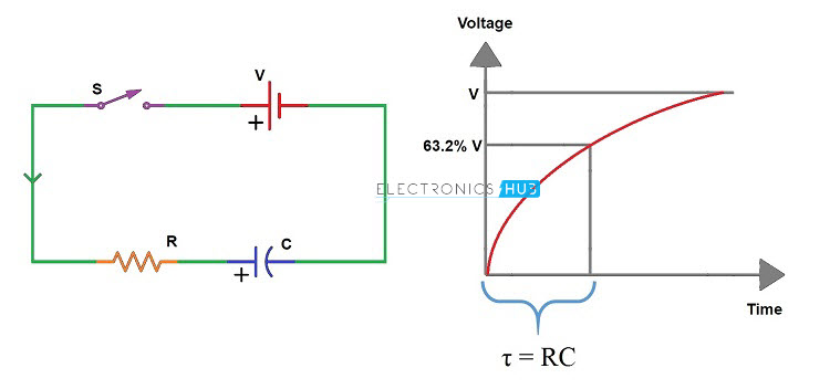 We use the same concept in our Arduino based Capacitance Meter. We will charge an unknown capacitor through a known resistance using Arduino pins and calculate the time it takes to reach 63.2 % of supply voltage (3.1 V approximately). Based on the time, we can calculate the Capacitance from the formula C = τ / R.
We will use a 10 KΩ Resistor to charge the capacitor and a 220 Ω Resistor to discharge it. The charge and discharge pins on Arduino are 8 and 9 respectively. The voltage across the capacitor is measured using the Analog Input pin A0.
Initially, we will discharge the capacitor using pin 9 (by setting it as OUTPUT and LOW) to make sure that the capacitor has no charge. We will then start the timer and charge capacitor using the charge Pin8 (by setting it as OUTPUT and HIGH).
Now, we have to monitor the voltage across the capacitor at the analog pin and once it reaches 63.2% of 5V (approximately 648 from analog pin), we have to stop the timer and calculate the capacitance.
This circuit is suitable for comparatively higher capacitance values as we can clearly measure the time constant. For smaller capacitance values, this circuit might not be suitable.


ความคิดเห็น
แสดงความคิดเห็น